
|
|
|
|
#1
 May 16th 2005, 10:06
|
||||
|
||||
|
911 Cooling Shrouds - Improving Internal Air Distribution
Hi all,
I have been playing around with this shroud for a few weeks now and along with my datalogger, have what I believe to be an accurate baseline to compare any modifications to my FAT 911 cooling setup. I'm using stock T4 under cylinder tins. I have tuned my engine the best I can and it seems to be running well. I have quite a few graphs produced by my logger and have noticed some interesting points: 1. With the unmodified shroud and stock 11 blade fan/ alternator ring, as the engine warms up, #1 and #2 warm up slower than #3 and #4. The slope of the graph for these temps over time indicate that #4 warms up twice as fast as #1. (Is #1 receiving twice as much cooling air as #4 ? :shrug: ) 2. After a hard run up to 140 kph from a dead stop, and then coming to a dead stop and idling (900 rpm) for 5 minutes ... #1 cools down twice as fast as #4. The cylinders seem to cool down with #1 cooling the fastest, then #2, #3 and then #4. #1 cools at the rate of -0.35F / Sec and #4 at -0.18F / Sec. 3. By taking the fanbelt off and starting the engine and letting it idle, all 4 cylinders warm up at the relatively the same rate ... making sure its not a tuning issue causing the temp imbalance. 4. Driving the car in 5th gear at 115kph (3000 rpm) vs 4th gear at 88kph (3000 rpm) creates temps 25 degF hotter (engine load im thinking) I'll post some pics of how the 911 alternator ring has 4 built in diverters that seem to direct airflow in this shroud. The airflow of a 911 axial fan spins clockwise and I have a cool picture of an axial fan showing the airflow pattern and air distribution in free air. My plan of attack is to place diverters on the back of the alternator (alternator cap ) similar to a stock 911-6 setup to start, and working with the alternator ring diverters So ... does anyone have any suggestions on how to equalize the airflow (swapping to a DTM does not count  ) ? I have my own ideas but it would be great to place all of this information in one thread, where everyone could benefit from this information. I'm not looking to market this product, just love the look and sound of this setup and want it to cool more effectively. ) ? I have my own ideas but it would be great to place all of this information in one thread, where everyone could benefit from this information. I'm not looking to market this product, just love the look and sound of this setup and want it to cool more effectively.Sandeep 
|
|
#2
May 17th 2005, 06:36
|
||||
|
||||
|
Hey Sandeep,
Cool idea, lets give Jake a head start for s/th he plans on doing in the future as well Funny, I experienced roughly about the same findings as you did. They are also consistent with the data that Jake had on his site (and this forum) AFAIK some time ago, just after his tests. I say roughly thesame, because my temp differences between 1 and 2 AND 3 and 4 were very close, but that may partly be due to the fact that I used (porsche 964) Nikasil cylinders. I also installed the stock diverter (it just fits a BAS shroud with only very minor mods) and even enlarged it. Utimately, it made nr. 4 cylinder run cooler than nr. 3 : Oeps  Since my oil temperatures kept a stunning 85 degrees Celcius (185F) at all revs (!) and since I believe that the cylinders are a major factor in cooling the oil (apart from the actual oil cooler of course) and because my top cylinder fins are very small, which creates a huge barrier for air to flow over the first cylinderhead fin, I went as far as to put an almost horizontal plate over the cylinders to increase flow towards and over the heads. I will have pics in a few days I hope. Anyway, that gave a 50F lower head temp! with the same oil temps. 1 and 2 are still lower in temp overall than 3 and 4, but that will be the goal for step 3  The difficulty is that there are a lot of factors into play here. For instance, I have used the 11-blade fan with the 245mm diameter blades and a 90mm pulley on the fan and a 140/145mm pulley on the crank. I have also tried the 12-blade fan which has a 100mm fan-pulley and 255-ish fan diameter. The 12-blade also has a totally different housing air-outlet; more straight than the 4 curved ones you spoke of. I have a picture of the latter one if you want it posted (I have before). I have done too little runs with the same conditions to be able to say s/th conclusive about the differences on that one yet. - end of report - (for now) Regards, Walter Last edited by Wally; May 17th 2005 at 06:42.
|
|
#3
May 17th 2005, 14:01
|
||||
|
||||
|
Wally,
Its great to hear you are having success with your 911 setup. I too believe that the stock 911-6 diverter on the back of the alternator is key. The 964 fan diverter is indeed a work of art, perhaps an improvement over the SC 11 blade setup. I have ordered an SC diverter, hope to have it in a few weeks. I will install it with mods if need be and see where my temps are going to end up. Up till now, my max temp difference between #1 and #4 are averaging 70 degF while 1-2 side and 3-4 side are up to 60 degF apart. 1-3 and 2-4 are 24 degF apart because 3-4 are higher than 1-2. Please post pics of that horizontal plate you are talking about .. would be interesting to see. Sandeep
|
|
#4
May 19th 2005, 11:16
|
||||
|
||||
|
Sandeep, the first step you should take would be to increase the drive ratio like we spoke about when I met you. This is easily done with the later model Porsche top pulley.
The shroud you are working with has a few physical challenges that will limit your work that can be done without actually modifying the shroud's skin. Your primary objective should be to effectively divert more air flow to the #2 and #4 cylinders as they are the hottest due to being almost directly under the fan and air generally does not like making a 90 degree bend... At least without being directed efficiently..... I am glad to see that you are making this development- You will undoubtedly see just how difficult air can be to manipulate, I never would have dreamed that it was so difficult to work with. The differences in temps arenot as great as I saw. This could be directly related to two things: One is your climate, its cooler where you are on ambient temps and also that your gearing may be shorter and not placing as much load on the engine thus not showing all the data to its max extreme. In some of my tests I installed 28" tall tires on my car to effectively gear the vehicle up to place more load on the engine and create more heat with less fan speed- thats when the differences really came out in the car just like they did on the dyno, and even more in some instances. Doing this allowed me to develop the TI shroud to even a higher level than most people would ever be able to push it to.. Also the smallest engine I tested was 153 BHP- Kep it up, you'll learn a ton!
__________________
Jake Raby
|
|
#5
May 19th 2005, 16:21
|
||||
|
||||
|
Sandeep,
This is the 12-blade backside:  Note that the original 964 cone is missing here (still need to get that one )I really like the way the air is directed out in a straigth way. Also that that is done by a multitude of air diverters, which are also longer overall than the 4 on the old fan houses. Theoretically, it would make it easier to divert the air to 3 and 4, if half the work is already done inside the fan housing! It would only be logical that porsche would upgrade its parts during the production of its aircooled boxers  Greets, Walter
|
|
#6
May 22nd 2005, 14:02
|
||||
|
||||
|
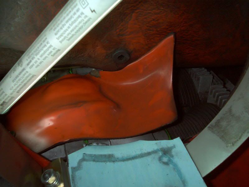
As promised, here's a picture of the original cone air deflector of a porsche 11-blade 245mm fan/alternator combo:
 And here's a preliminary air deflector I made to direct more air to the heads and to overcome the barrier of the first cooling fin. This is because the fins on the nikasil 964 cylinders I use are very small (therefore low, so the heads fins stick out a lot). It gave a 50F lower head temp The 964 cylinders have M6 thread on top of the cylinders, so I could mount to that. Originally on the porsche 964 those holes are for mounting the knock sensor bridge...  The original air deflector/cone did gave slightly lower head temps for 3 and 4, but not as much as I thought they would. Enlarging the area of the cone air deflector did work, but still not enough to my liking compared to the temps of 1 and 2. Work in progress Walter
|
|
#7
June 16th 2005, 10:18
|
||||
|
||||
|
Quote:
.. not sure how much more though or if it is significant.Quote:
Quote:
Sandeep
|
|
#8
December 31st 2007, 11:46
|
|||
|
|||
|
What you are talking about if bifurcating the output of the 911 fan.
It would look just like the annular cans in my old turbine engines. Looking from the rear, they would be split at 1 o'clock and 7 o'clock, with the 1 and 6 o'clock tube feeding the 3/4 cyls and the 12 and 7 o'clock tube feeding the 1/2 side. I have made up foam models to do this, as it is an excellent idea, but I have no fiberglassing savvy. Maybe a fiberglassing GURU close to me would like to take on the challenge of taking my foam molds and making fiberglass molds to test and share the results? OF course, since it would be the most beautiful and efficient design/use of the 911C2 fans(12-blade), demand will be so great that one person couldn't possibly spend all the cash he would make off of my idea/molds, so he would also share some of the profits, eh? BUWAHAHAHAHAHAHAHAHAHAHAHA! Interested Wally? Don Last edited by dstar5000; December 31st 2007 at 11:48.
|
|
#10
January 4th 2008, 04:55
|
||||
|
||||
|
http://www.rbernauer.de/
RMB=Renn Motoren Bernauer It is said he is developing the 4-valve aircooled head together with Martin Bott From their site: 
Last edited by Wally; January 4th 2008 at 05:03.
|
|
#12
January 6th 2008, 21:01
|
||||
|
||||
|
Very interesting Wally.
It does look like the air is being forced between the cylinders on both sides of the engine, with a portion of the air split between the head. Do you know how much development went into this shroud ? I'll be restarting the work on my shroud as soon as the 2.4 is together and running, as I am using new cylinders. Thanks for the pics ! *** Don *** I like your idea too about splitting the air into quadrants and directing to a portion of the engine. Sandeep
|
|
#13
January 7th 2008, 10:56
|
|||
|
|||
|
Wally
What are the chances that you got a picture of that shroud from the front? (where you mount the fan, looking into the shroud)
__________________
1969 VW aka Suicyde www.geocities.com/suicyde_vw Tony__Z@hotmail.com
|
|
#15
January 7th 2008, 16:40
|
||||
|
||||
|
Very cool Eugene!
By the looks of it, you also have the special welded-up heads from Rolf Klaus! Could you give more info on these heads and what motor you use them on? What version of the Klaus cooling system is yours? Thanks, Walter PS Sorry , don't hav emore pics or info on the GWD type 1 shroud, but its around for quite some time now..
|
 |
| Currently Active Users Viewing This Thread: 1 (0 members and 1 guests) | |
|
|


 Hybrid Mode
