
|
|
#1
 December 12th 2007, 21:35
|
||||
|
||||
|
Fitting a 5 speed into your bug
I have collected enough info for an article that I have done in PPT but its to large probably to host as a pdf.. but will post some of the high lights in this thread.
Slide 1- 5-Speed Conversion: Installing a Porsche Gearbox into your Type I IRS Chassis Slide 3- Starting Point: In order to install a 5 speed gearbox you must first begin by locating one. For this conversion the following gearboxes are acceptable starting points 901 and 902 (5 Speed) 901/911 and 914 gearbox 915 For this guide we will discuss the 901/902/914 family of gearboxes. The 915 will follow the basic procedure Slide 4- Distinguishing Porsche Gearboxes 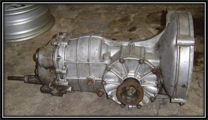 This is an example of an early 911 gearbox. (used in the 911 from around 1965to 1968) These boxes are referred to as 901 boxes. Identification marks are located on the bottom of the gearbox The 902 boxes are identical to the 901. It was found in early 912, and has the same internals as the 901 but different ratios Slide 5- Distinguishing Porsche Gearboxes (Cont) Early 901 Transmissions Were made of Aluminum 65 to 68. These boxes had a Push Type Clutch Slide 6 Distinguishing Porsche Gearboxes (Cont) 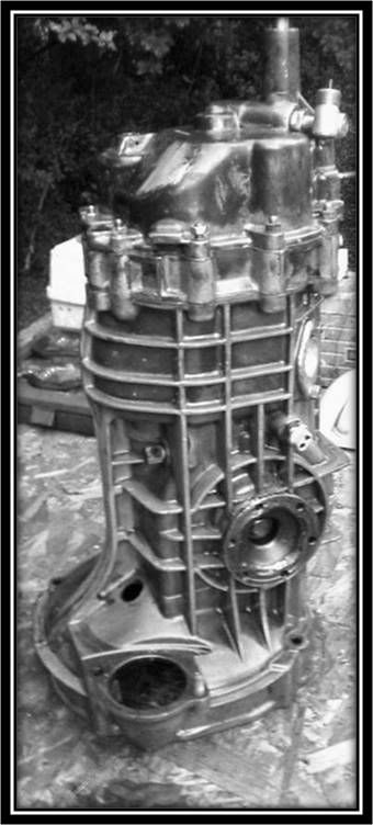 (Picture from another board member) (Picture from another board member)Late 901 transmissions : Were made of magnesium 69 to 71 1969 continued to utilize the Push Type Clutch 70 to 71 utilized a Pull Type Clutch Slide 7 Distinguishing Porsche Gearboxes (Cont) 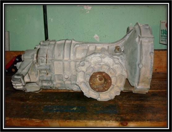 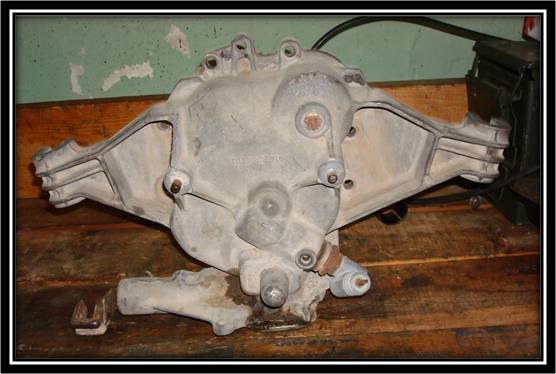 914 Tail Shift Transmission Found in 914 Porsches (pre-1973 914/4 and 914/6) Slide 8 Distinguishing Porsche Gearboxes (Cont) 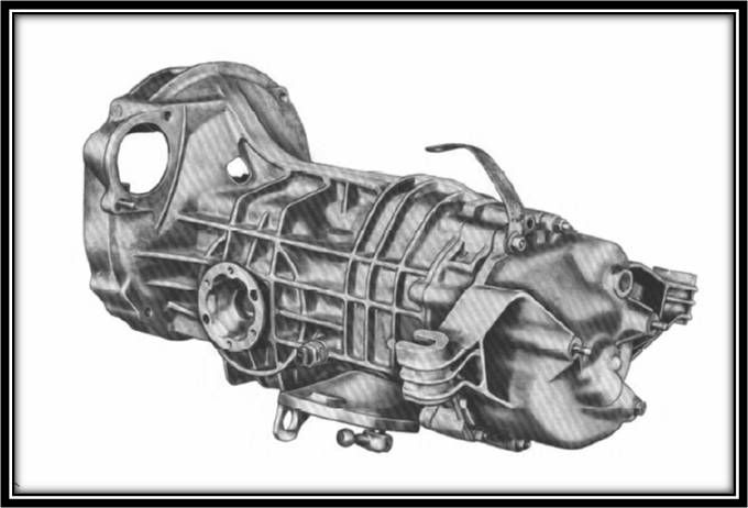 914 Side Shift Transmission Late 914 utilized the side-shift configuration. Look at the similarities in the case to the tail shift. Nose cone and shift rod and fork internals differ The 914 Side Shift transmission can still be utilized for the conversion but will require additional work and components
__________________
Alex Olaverri Sales Associate for Bug@5-Speed (US) Email: Bugat5speed@yahoo.com Tele: 973 204-5463 
|
|
#2
December 12th 2007, 21:51
|
||||
|
||||
|
Bug@5-Speed Kit Components
Slide 9 Bug@5-Speed Kit Components
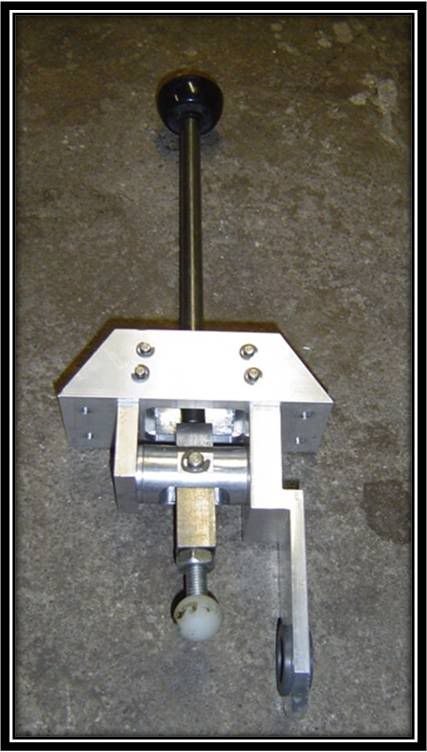 Bug@5-Speed Beetle Shifter The Shifter can be looked as a short throw shifter, due to the reduction in shifter throw. The base of the shifter provides additional support for the beetle shift rod as well as a bushing for the beetle rod to ride smoothly on. This support eliminates a lot of the issues that some folks may have due the bending their bug shift rods like a Z or are not having the proper alignment. With the supported shift rod, proper alignment from the shifter to the input shaft on the Gearbox is maintained. -Shifter has spring gate to prevent accidental shifting into reverse. Can use with a stock, aftermarket or our shifter ball. Slide 10 Bug@5-Speed Kit Components 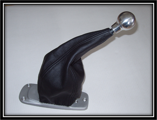 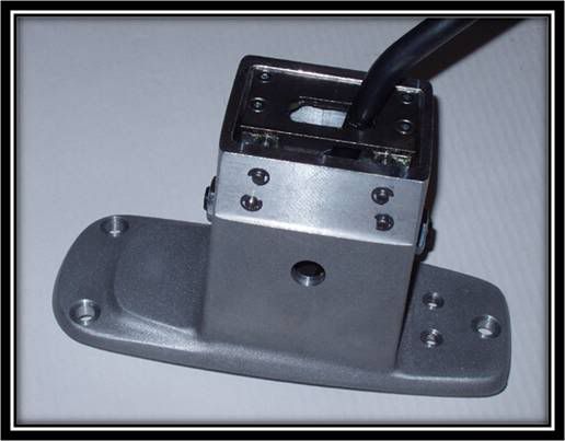 Bug@5-Speed Porsche Style or aka Square Shifter This Shifter is similar to the beetle style but with obvious differences. Shifter comes with a 911 style base to attach to a Porsche tunnel or modified beetle tunnel Additionally comes with bent shift rod, leather boot, and machined shift knob. This shifter can also be looked as a short throw shifter, as the shifter has a throw of less than 60 mm per gear. The Shifter has spring gate to prevent accidental shifting into reverse. Can use with a stock, aftermarket or our shifter ball. Slide 11 Bug@5-Speed Kit Components Bug@5-Speed Front Traverse 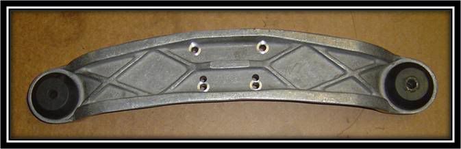 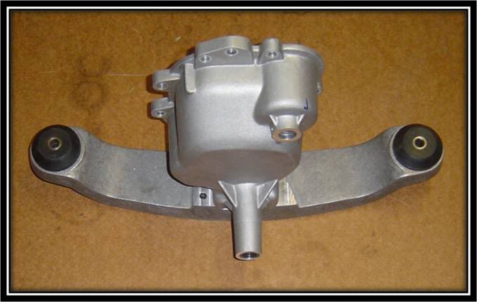 Cast Aluminum, with Hardened Black Mounts Creates mounting point for Nose Cone. Attaches to the based of the IRS mounts via special wedge spacers and M12 sized bolt Slide 12 Bug@5-Speed Kit Components Bug@5-Speed Nose Cone 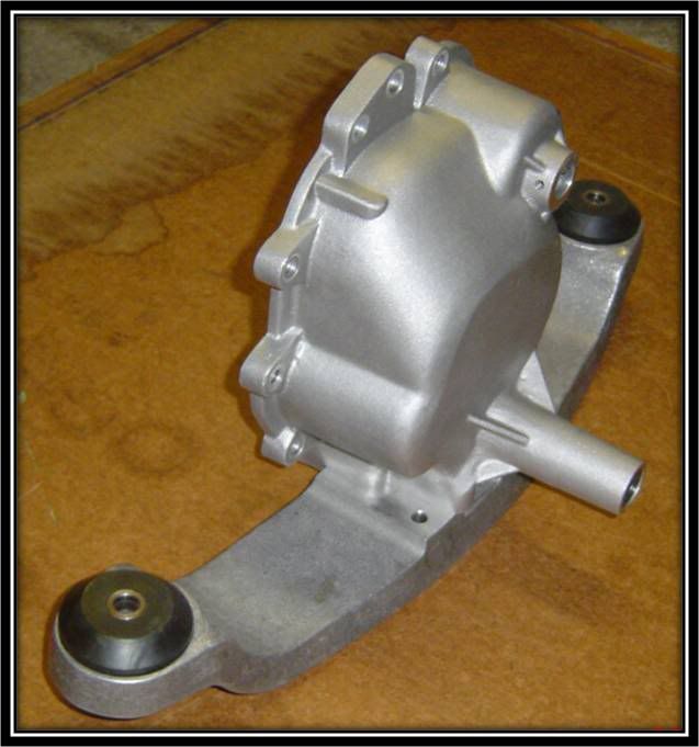 Cast Aluminum, and machine finished. The nose cone allows the transmission to be moved fwd 30 mm thereby giving you more space out back and providing better weight distribution. Slide 13 Bug@5-Speed Kit Components Bug@5-Speed Rear Support 901 Style 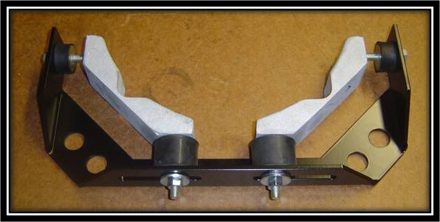 914 Style 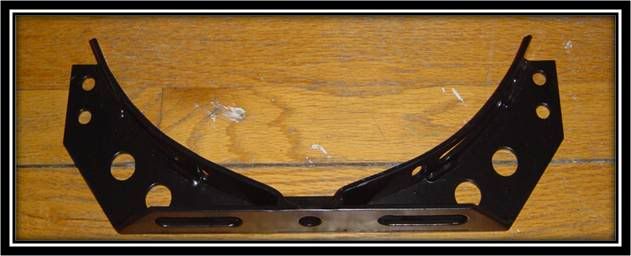 There are two designs due to the shape of the gearbox bell housing shape 901 style is designed to attach to 901 and 915 bell housing which dont have the flat sections that the 914 s have 914 style is designed to attach to the bell housing via beetle rear transmission mounts Slide 14 Bug@5-Speed Kit Components Bug@5-Speed Clutch Cable adapter plate and Cable Extension Connector 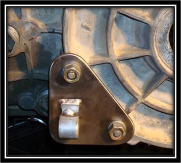 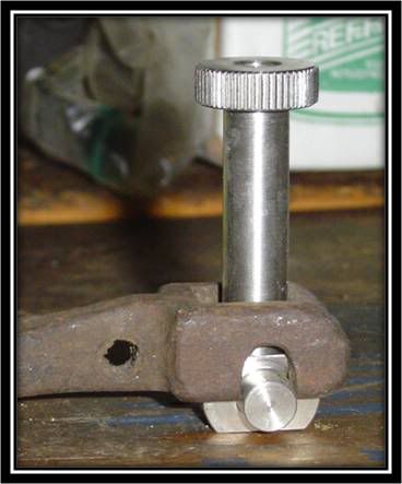 Adapter Plate is needed due to the lack of an eyelet to secure Bowden Tube and maintain proper alignment Cable Extender attaches to the end of the factory clutch cable enabling quick adjustment by turning knurled bit
__________________
Alex Olaverri Sales Associate for Bug@5-Speed (US) Email: Bugat5speed@yahoo.com Tele: 973 204-5463
|
|
#3
December 12th 2007, 21:53
|
||||
|
||||
|
Components (Continue)
Slide 15 Bug@5-Speed Kit Components
Bug@5-Speed also carries Inner Shift Forks for use when converting 914 tail and side shift gearboxes 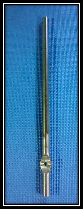 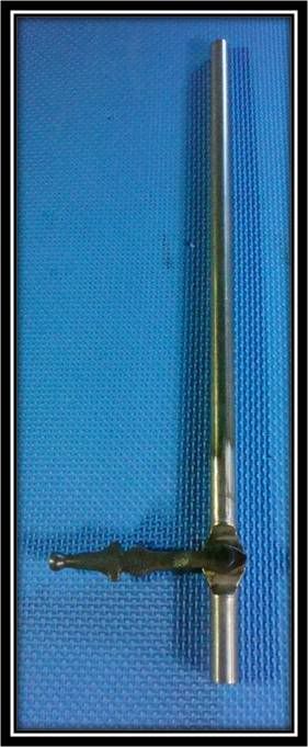 Slide 16 Bug@5-Speed Kit Components Bug@5-Speed also carries Modified 901 and 914 TOB Forks for use when converting 901, 914 tail and side shift gearboxes Modified forks are bent to provide better geometry These can be purchased on an exchange basis Lever is newly galvanized after the modification/adjustment*and equipped with a new guiding socket at the back.* 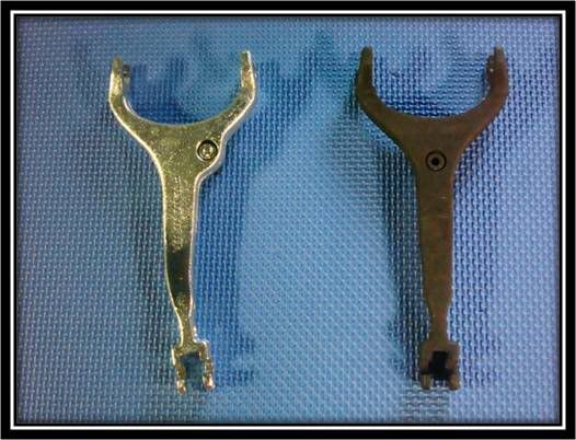  Slide 17 Bug@5-Speed Kit Components Bug@5-Speed Gearbox Output Flanges 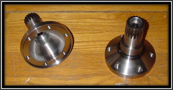 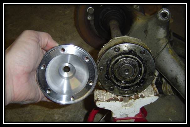 Come in two sized: Stock Beetle diameter (78mm) 944/T2 diameter (86mm) Machined and Hardened Note: early 901 flanges have larger opening and must be specified
__________________
Alex Olaverri Sales Associate for Bug@5-Speed (US) Email: Bugat5speed@yahoo.com Tele: 973 204-5463 Last edited by Bug@5speed(US); July 17th 2008 at 21:22.
|
|
#4
December 12th 2007, 22:26
|
||||
|
||||
|
Slide 19- Getting Started (Partial Disassembly)
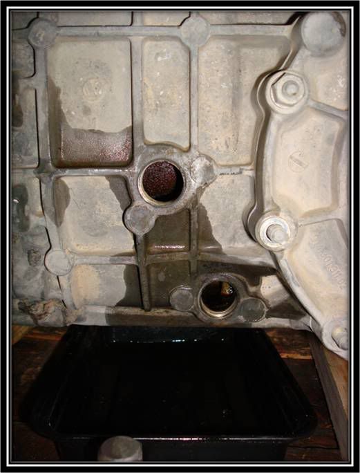 Drain oil via two plugs on the side of the gearbox (17mm Hex Drive) Lower plug is magnetized to capture filings It is a good idea to inspect this plug to have an initial idea of condition of internals Slide 20 Getting Started (Partial Disassembly) 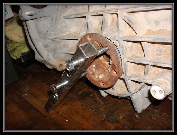 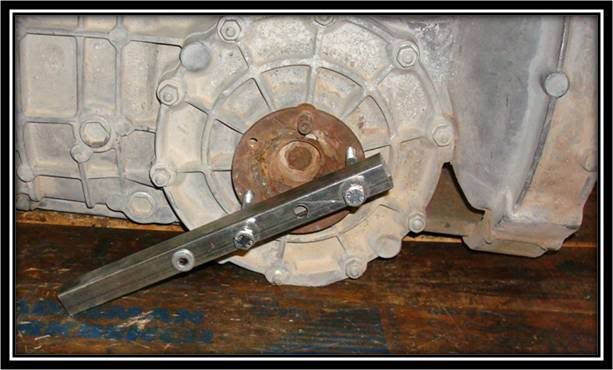 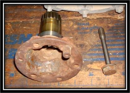 Removing Flanges Utilizing 1 inch square stock special tool is made to prevent flange from spinning Bolt on flanges are size 19mm and are referred to as diff expansion bolts Slide 21 Getting Started (Partial Disassembly) 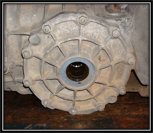 The differential side cover/plate is secured by 13mm sized nuts Removing of the side cover is necessary in order to flip the differential This is necessary on the 914 gearboxes due to the 914 boxes being set up for mid engine configuration Failing to due this will yield one fwd gear and 5 reverse gears Slide 22 Getting Started (Partial Disassembly) 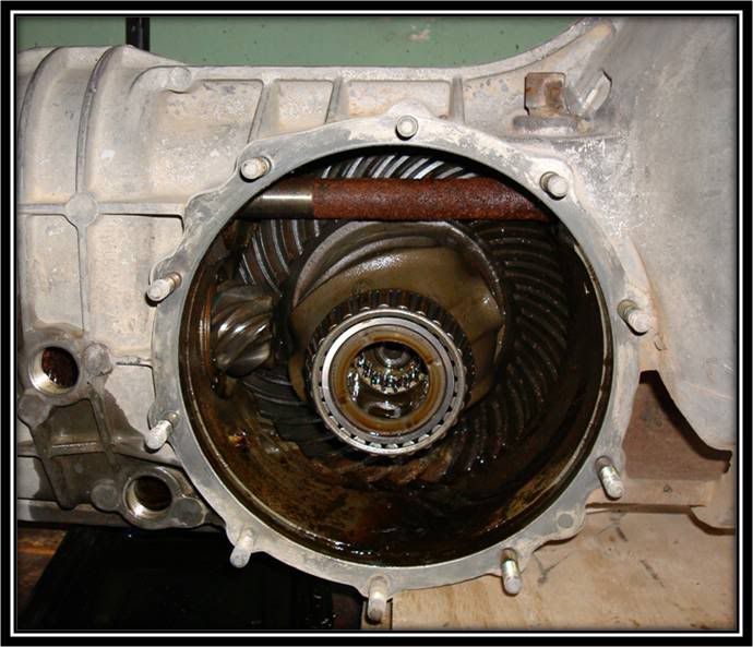 Side Cover removed exposing a poorly maintained gearbox This is not what you want to find With cover removed it becomes evident that in order to remove the diff, the pinion shaft and main shaft will have to be removed Slide 23 Getting Started (Partial Disassembly) 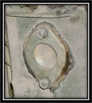 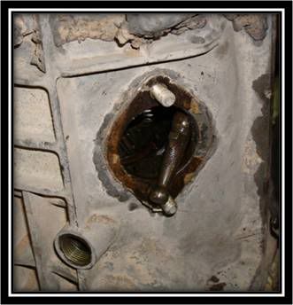 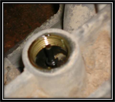 Few more items that need to be removed to enable the intermediate plate, and gear stack to be pulled away from the case to access diff Unbolt 2 13mm nuts to removed side cover plate; freeing inner shift rod Removed reverse gear switch and pin
__________________
Alex Olaverri Sales Associate for Bug@5-Speed (US) Email: Bugat5speed@yahoo.com Tele: 973 204-5463
|
|
#5
December 12th 2007, 22:37
|
||||
|
||||
|
Getting Started (Partial Disassembly) (Continue)
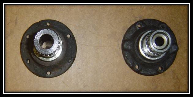
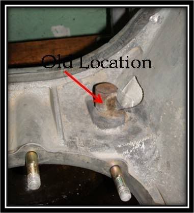
Slide 24 Getting Started (Partial Disassembly)
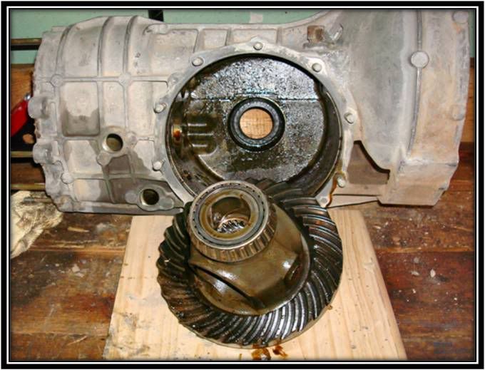 With the intermediate plate and gear stack out of the way you can now pull the differential from the box Now reinstall with differential Ring Gear facing the opposite way Reinstall all items in reverse Slide 25 Getting Started (Partial Disassembly) 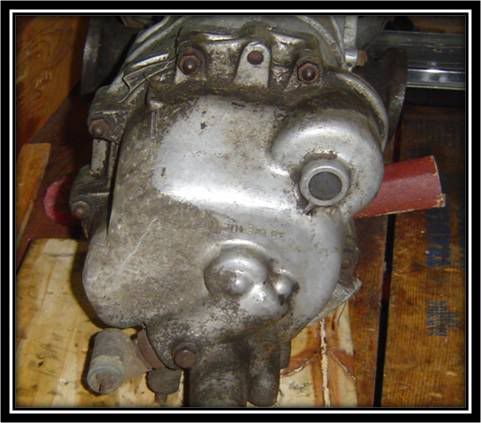 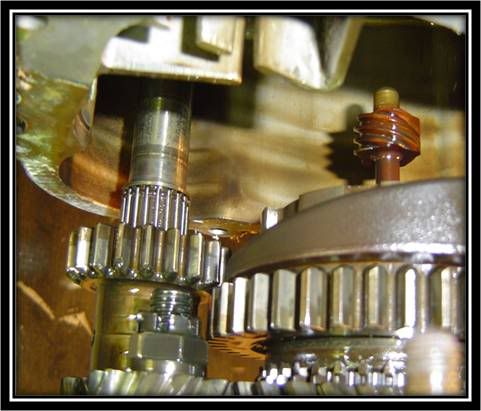 Nosecone is secured to intermediate plate via 13mm nuts. Once nuts are removed utilize a rubber mallet to remove nosecone Take caution when removing the nosecone, as the reverse gear assembly may fall out/off Slide 26 Getting Started (Partial Disassembly) 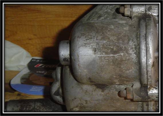 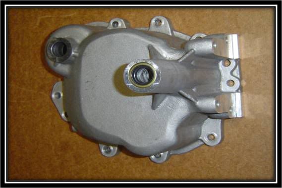 With cover removed now is a good time to transfer reverse gear shaft onto your new nosecone Example shown of early 901 nose cone Utilize a small punch and remove small pin Remove reverse shaft and relocate onto Bugat5speed Nosecone Reinsert small pin to secure/lock reverse gear shaft Slide 27 Getting Started (Partial Disassembly) 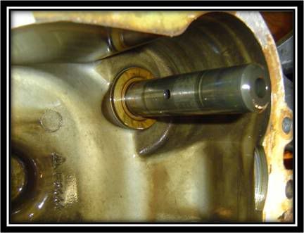 Reverse Gear shaft shown on the old nose cone 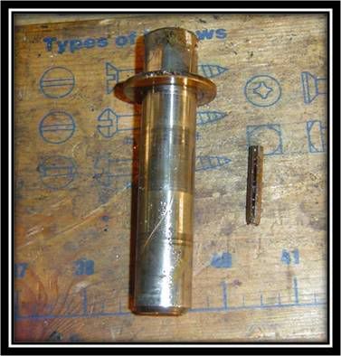 Reverse Gear shaft and locking pin
__________________
Alex Olaverri Sales Associate for Bug@5-Speed (US) Email: Bugat5speed@yahoo.com Tele: 973 204-5463
|
|
#6
December 12th 2007, 22:40
|
||||
|
||||
|
Getting Started (Partial Disassembly) (Continue)
Slide 28 Getting Started (Partial Disassembly)
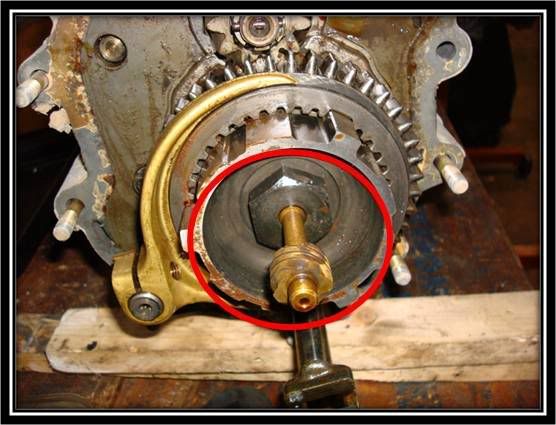 With Nose Cone removed, now is a good time to remove the speedometer drive gear Two approaches (1) Use a hacksaw and cut (Not best approach) or (2) Remove Expansion bolt (held in place with (80-87ft/lbs) and decouple drive gear (Better approach) Slide 29 Getting Started (Partial Disassembly) 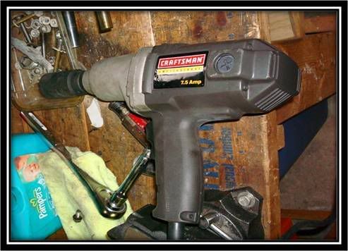 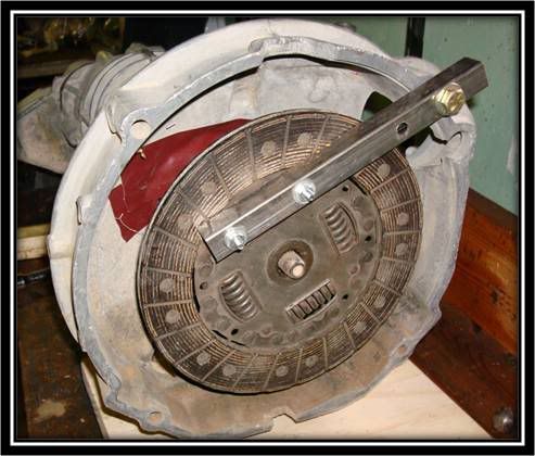 The Expansion bolt is size 32mm, and will require that you lock the gearbox down in order to utilize an impact drill to remove. There are many methods to locking the gearbox, one such method is to utilize an old clutch disk, using some one inch stock and a few bolts (See side picture) Slide 30 Getting Started (Partial Disassembly)  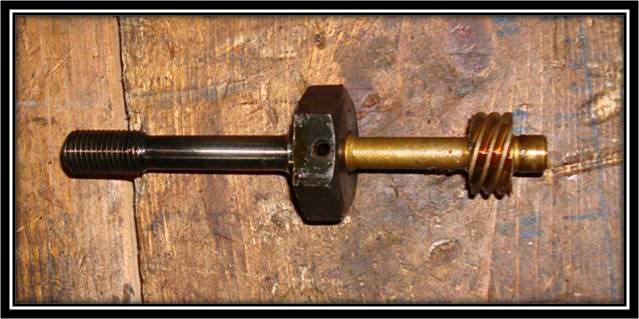 Once expansion bolt is removed from, you will notice that the speedometer drive gear is secured via a small pin To separate remove lock pin Slide 31 Getting Started (Partial Disassembly) 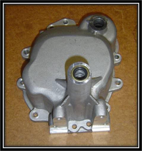 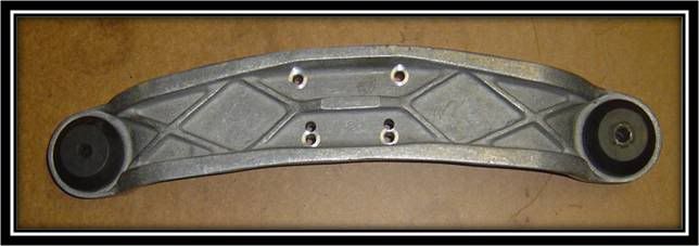 The Bug@5-Speed Nose Cone and Front Traverse are shown on the right. With the reverse gear shaft installed and locked in, you can attach nose cone to the intermediate plate and gearbox. Be sure to replace the factory gasket or utilize a liquid gasket to create a good tight seal Secure to gearbox with the self-locking nuts and washer Torque 13mm nuts to 18 ft/lbs (Per Porsche Manual
__________________
Alex Olaverri Sales Associate for Bug@5-Speed (US) Email: Bugat5speed@yahoo.com Tele: 973 204-5463
|
|
#7
December 12th 2007, 22:43
|
||||
|
||||
|
Getting Started (Partial Disassembly) (Continue)
Slide 32 Getting Started (Partial Disassembly)
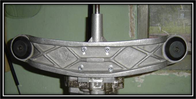 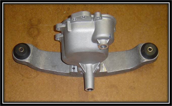 The Front Traverse is secured to the nose cone via (4) hex bolts This is what the final nose cone and traverse should look like. Slide 33 Getting Started (Partial Disassembly) Bowden Tube/Clutch Cable Adapter Plate Install (914) 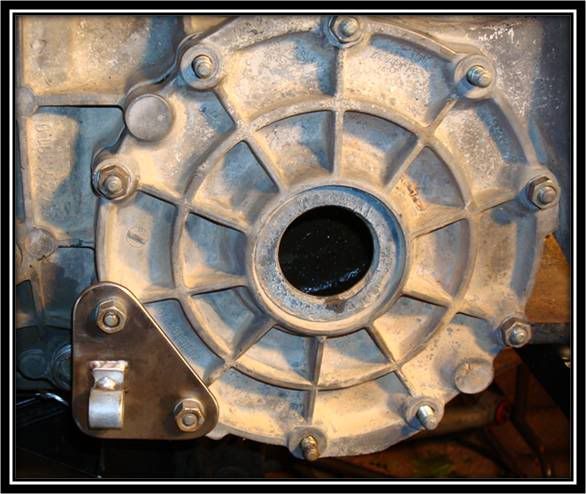 The Adapter Plate is utilized to redirect and establish proper geometry for the clutch cable and Bowden tube Install is accomplished by placing adapter plate onto differential side cover via two 13mm nuts Shown is install on a 914 gearbox Slide 34 Getting Started (Partial Disassembly) Bowden Tube/Clutch Cable Adapter Plate Install (901) 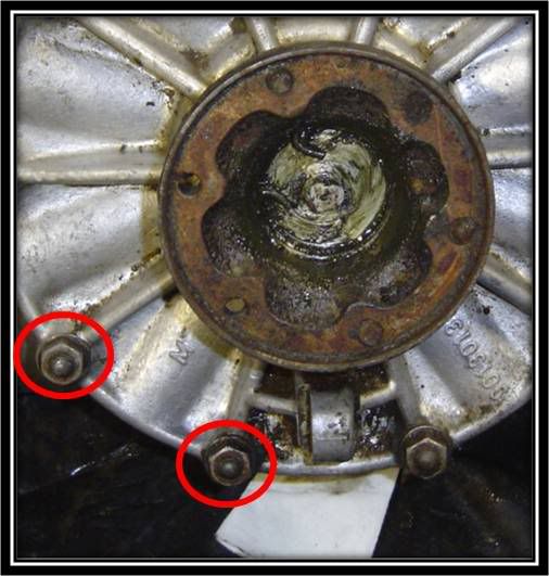 While the 901 early gearbox has an eyelet for the clutch cable, this is not the optimal setup. It is recommended to use the Bug@5-Speed Adapter Plate. The Plate is utilized to establish the proper geometry for the clutch cable and Bowden tube Install is accomplished by placing adapter plate onto differential side cover via two 13mm nuts Removal of the 901 eyelet will be necessary. This can be accomplished by cutting the old eyelet and plugging hole with automotive plug Failure to plug hole will yield hole in side cover Slide 35 Getting Started (Partial Disassembly) 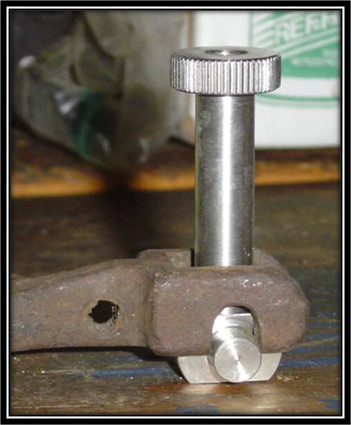 In order to attach the cable extender to the 901 or 914 Tob Fork, you need to attach the adapter piece which will serve as a guide for the knurled extension
__________________
Alex Olaverri Sales Associate for Bug@5-Speed (US) Email: Bugat5speed@yahoo.com Tele: 973 204-5463 Last edited by Bug@5speed(US); December 13th 2007 at 21:54.
|
|
#8
December 13th 2007, 22:05
|
||||
|
||||
|
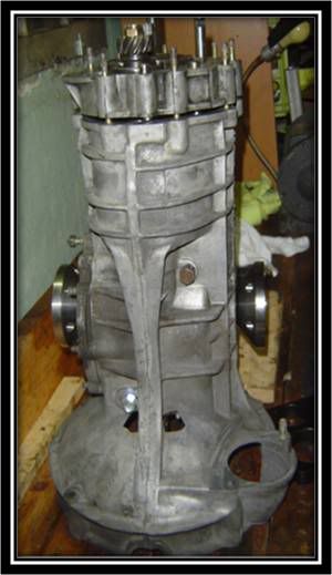
Slide 36 Bug@5-Speed Rear Gearbox Support
 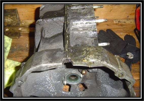 This is the bell housing side of the gearbox. The rear gearbox support is attached to the bell housing via beetle transmission mounts. It is affixed to the two flat areas on the bell housing Slide 37 Bug@5-Speed Rear Gearbox Support (Cont) 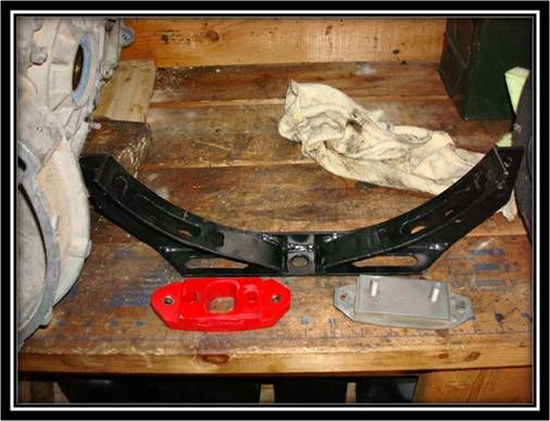 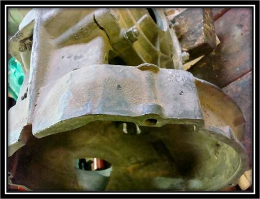 Both variety of transmission mounts can be used with the Bug@5-Speed Traverse To begin the installation process, you must mark where the attachment holes will need to be Slide 38 Bug@5-Speed Rear Gearbox Support (Cont) 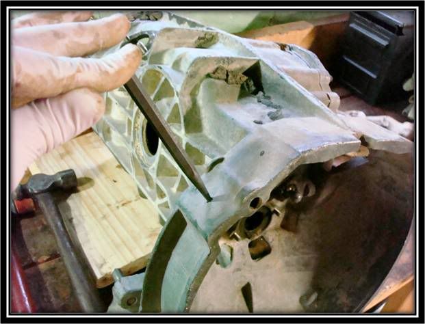 With the bell housing marked, use a punch and hammer, to mark the pilot holes for the drill bit Slide 39 Bug@5-Speed Rear Gearbox Support (Cont) 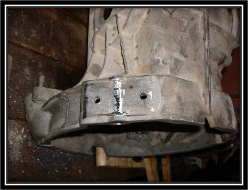 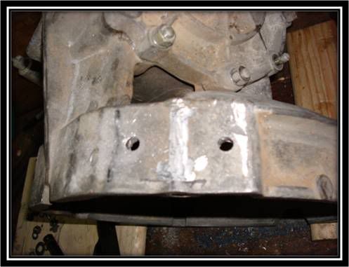 With the 4-holes drilled into the bell housing, the next order of business is to utilize a grinder or dremmel with grinding bit to create a flush mounting surface for the transmission mounts Slide 40 Bug@5-Speed Rear Gearbox Support (Cont) 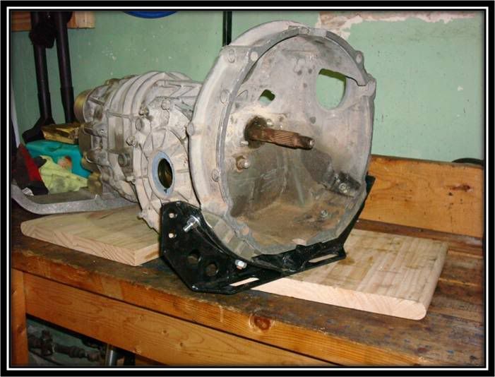 The last order of business is to attach everything to the bell housing with the manufactured supplied bolts/nuts or grade-8 or better hardware
__________________
Alex Olaverri Sales Associate for Bug@5-Speed (US) Email: Bugat5speed@yahoo.com Tele: 973 204-5463
|
|
#9
December 13th 2007, 22:06
|
||||
|
||||
|
Bug@5-Speed Output Flange
Slide 41 Bug@5-Speed Output Flange Install
   When ordering its important to know if you have the early 901 sized flanges (Large) or 914 flanges (Small) due to the different sized hole in the flange. Bug@5-Speed Flanges are affixed to the differential with the removed washer and expansion bolt (It is recommended that you replace bolts with new ones Tighten to recommended manufacture specification
__________________
Alex Olaverri Sales Associate for Bug@5-Speed (US) Email: Bugat5speed@yahoo.com Tele: 973 204-5463
|
|
#10
December 13th 2007, 22:18
|
||||
|
||||
|
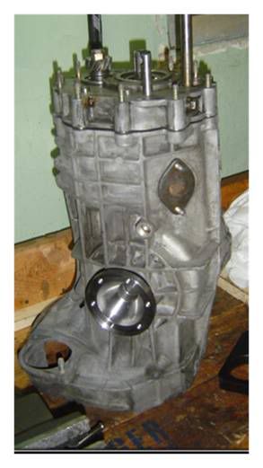
Relocating Oil Breather
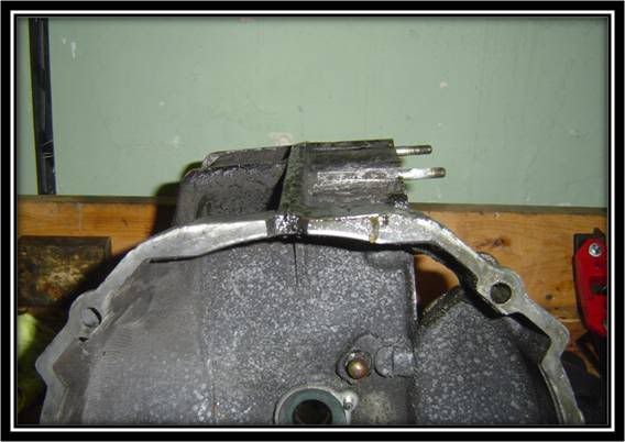
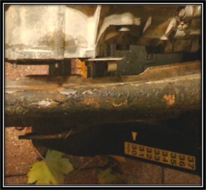
Slide 42- Relocating Oil Breather
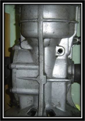  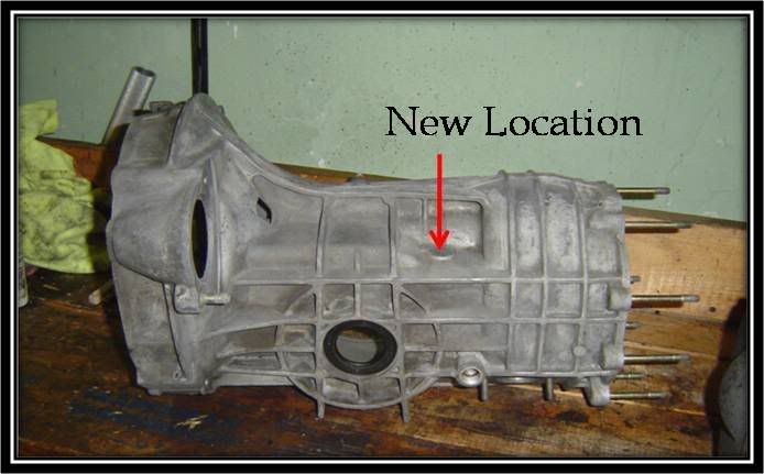 When using a 914 box it is necessary to relocate the oil breather tube to the same location as it would be found on a 901 box Bottom picture shows where the new location will be on the 914 box Slide 43- Relocating Oil Breather (Cont) 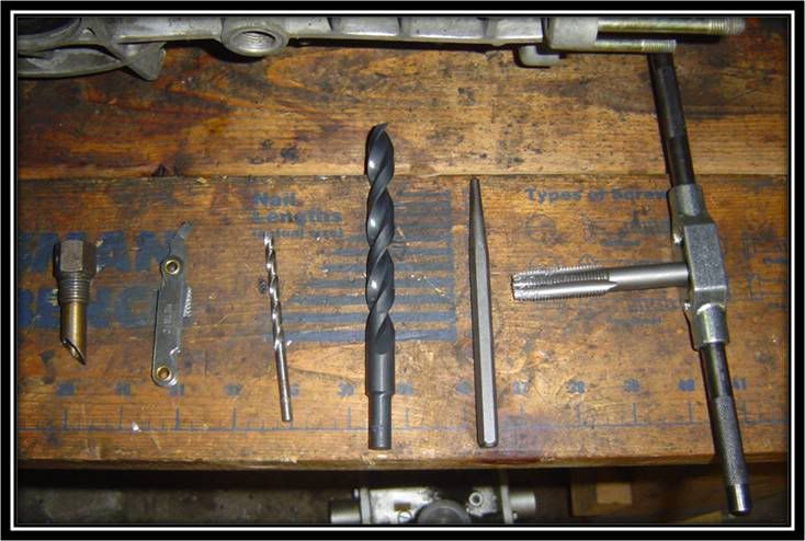 Some of the tools you will need to accomplish this task: Oil Breather Thread Pitch gauge Small drill bit for pilot hole Large bit Punch Tap and Handle Note: Remember your safety equipment (eye protection) Slide 44- Relocating Oil Breather (Cont) 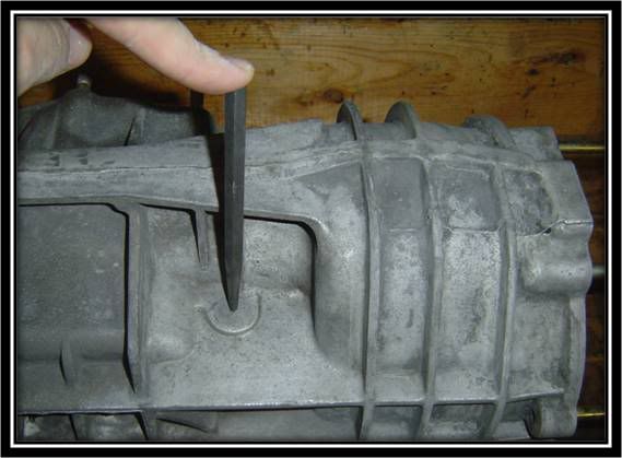 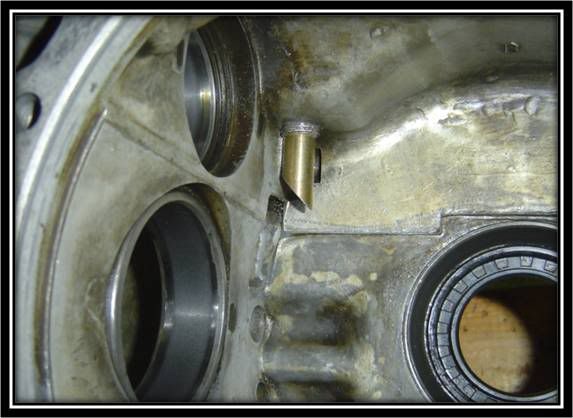 Use a Punch to mark the new location of oil breather tube Ensure new location of tube clears case internals Slide 45- Relocating Oil Breather (Cont) 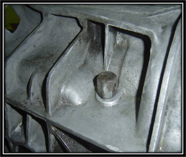 Use a small drill to create pilot hole Use appropriate large drill to open up hole to correct size for tapping Use gauge to verify correct tap size Using cutting oil, and tap with handle cut new threads onto case Slide 46- Relocating Oil Breather (Cont) 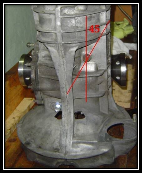 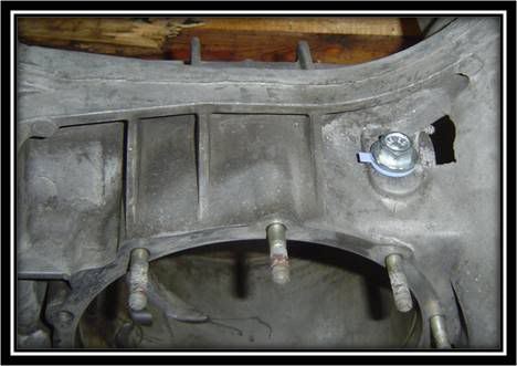 Lastly fit breather into new location. Breather should have approximately 45 degrees offset Plug old hole with automotive plug Oil Plug can be used
__________________
Alex Olaverri Sales Associate for Bug@5-Speed (US) Email: Bugat5speed@yahoo.com Tele: 973 204-5463
|
|
#11
December 13th 2007, 22:22
|
||||
|
||||
|
Type I IRS Chassis Prep
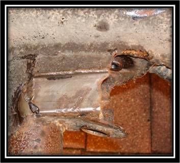
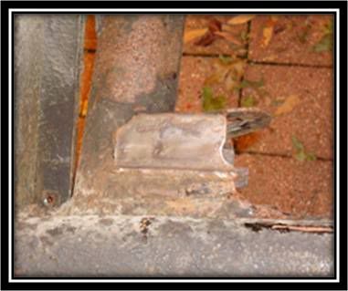
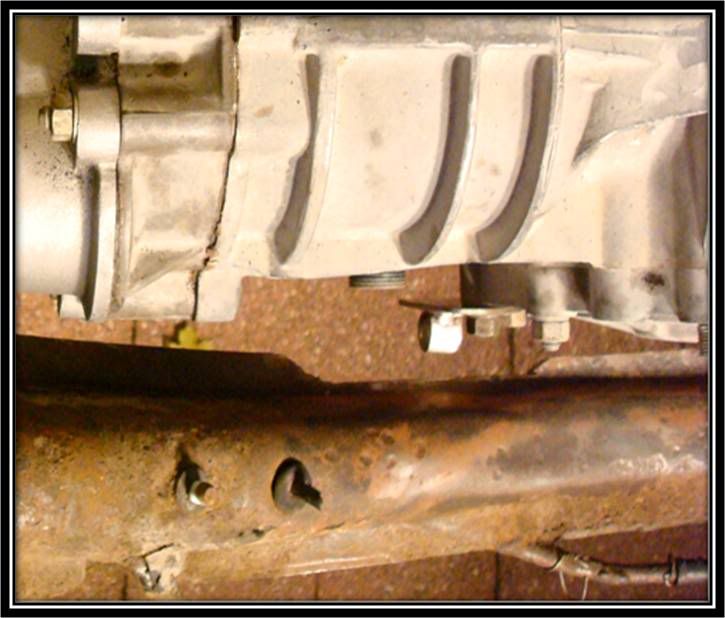
Slide 46 Type I IRS Chassis Prep
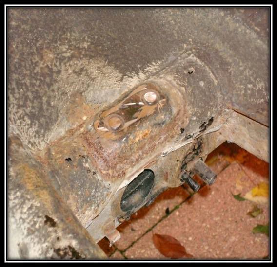 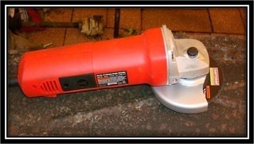 Installing the Bug@5-Speed Conversion kit can be done with body on or off. When installing the kit, it will be necessary to remove the old beetle transmission mounts as shown in the top picture A grinder and some eye protection make quick work of the transmission mount bolts This is what chassis should look like after bolts are ground off and surface made flush That's it for today.. Tomorrow the rest of chassis prep Enjoy and comments always welcome. Alex
__________________
Alex Olaverri Sales Associate for Bug@5-Speed (US) Email: Bugat5speed@yahoo.com Tele: 973 204-5463
|
|
#12
December 16th 2007, 16:26
|
||||
|
||||
|
Lots of good info here... but let me add a $$$$ tip: Use Loctite on all bolts and nuts on initial thighting! or they wil vibrate loose.
Cant wait to pick up my parts and start the conversion! Going to visit Martin in January. Last edited by Turbo Haraune2; December 16th 2007 at 16:28.
|
|
#13
December 17th 2007, 19:05
|
||||
|
||||
|
Thanks for the reminder.. Very true..
You'll have fun over at Martin's..
__________________
Alex Olaverri Sales Associate for Bug@5-Speed (US) Email: Bugat5speed@yahoo.com Tele: 973 204-5463
|
|
#14
December 17th 2007, 19:13
|
||||
|
||||
|
Slide 49- Type I IRS Chassis Prep
  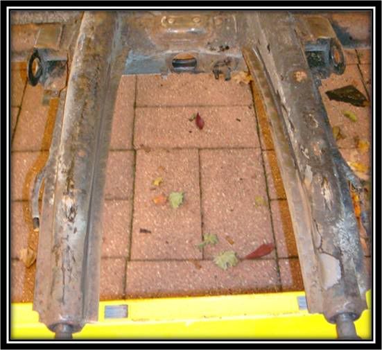 With 30+ years of grim and dirt, now is a good time to wire-wheel and clean the bottom of the IRS mounts Also clean the flat section of the frame horns This will help with test fitting the gearbox and when you need to identify areas that need to be clearance Slide 50- Type I IRS Chassis Prep 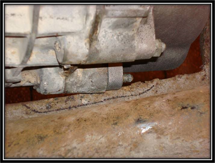 One of the first areas that you will notice that needs to be marked for clearance is the right hand side of the nosecone/intermediate plate (looking from top of chassis) Slide 51- Type I IRS Chassis Prep 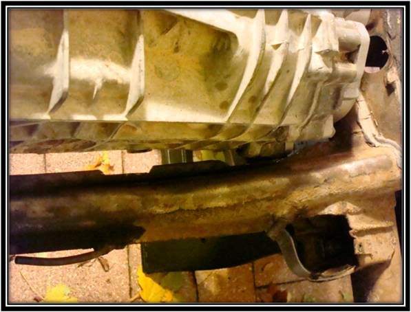 Shown here is the clearance for the reverse gear switch Slide 52- Type I IRS Chassis Prep 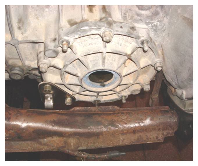  Shown is the clearance for the Clutch Cable Adapter Plate and for the TOB Fork
__________________
Alex Olaverri Sales Associate for Bug@5-Speed (US) Email: Bugat5speed@yahoo.com Tele: 973 204-5463
|
|
#15
December 17th 2007, 19:22
|
||||
|
||||
|
Slide 53- Type I IRS Chassis Prep
  Few more pictures of clearance for Clutch Cable Adaptor Plate Slide 54- Type I IRS Chassis Prep  Once all the clearances have been cut into the frame horns, this is what your chassis should look like. 1-Clearance for the intermediate plate 2-Clearance for shifter cable adapter plate & Bowden tube 3-Clearance for TOB fork 4-Clearance for reverse gear switch (optional) Slide 55- Type I IRS Chassis Prep 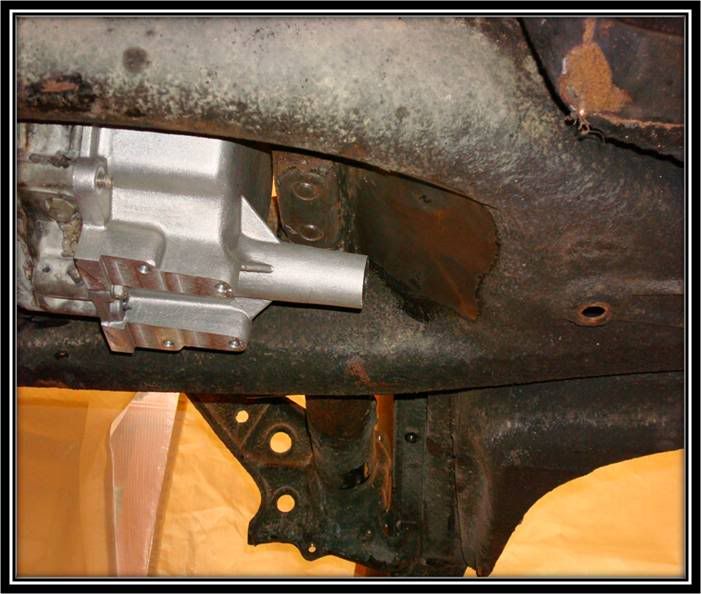 Gearbox is situated between frame horns to begin marking area to be cut for the inner shift-rod that will enter tunnel in the new location Slide 56- Type I IRS Chassis Prep  Using a wire wheel, area to be cut was cleaned to enable marking of the necessary patter for the shifter coupling to fit through the tunnel: Porsche Shifter Coupling requires hole cut to 60mm x 120m If using a VW Shifter Coupling it requires hole cut to 70mm x 120mm, due to larger size Slide 57- Type I IRS Chassis Prep 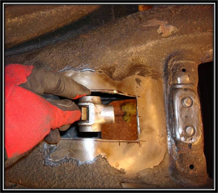 Once the hole is cut this is where the shift rod will enter tunnel. Notice the Porsche Shifter coupling Slide 58- Type I IRS Chassis Prep 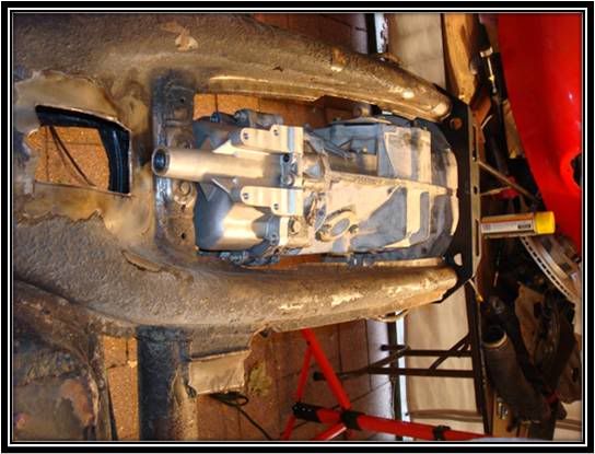 With shifter coupling hole cut, its now time to center our attention onto the front traverse, and the IRS mounts which serve as the mounting point for the gearbox Slide 59- Type I IRS Chassis Prep  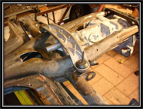 With the gearbox installed with the front and rear traverse, we will mark the location for the bolts to attach to the IRS mounts.
__________________
Alex Olaverri Sales Associate for Bug@5-Speed (US) Email: Bugat5speed@yahoo.com Tele: 973 204-5463
|
 |
| Currently Active Users Viewing This Thread: 1 (0 members and 1 guests) | |
|
|


 Linear Mode

